How Long Does Compression Molding Take? | Compression Molding Process & Cycle Time?

Learn how long compression molding takes, the factors affecting cycle times, and how to optimize compression molding processes for efficiency.

Compression molding is a widely used manufacturing process for producing high-strength components from composite materials, thermoplastics, and thermoset plastics. The time it takes to complete one molding cycle—known as the cycle time—varies depending on several key factors. In this article, we will explore what influences compression molding time and how long it typically takes to complete a compression molding process.

Factors That Affect Compression Molding Time

Several factors can affect the length of a compression molding cycle. Below are the most important considerations:

  • Material Type: Thermoset materials like SMC (Sheet Molding Compound) and BMC (Bulk Molding Compound) usually take longer because they require curing. Thermoplastics generally have shorter molding times because they do not need curing.
  • Mold Design: Complex mold designs with intricate shapes take more time to fill and cure. Efficient mold design can minimize cycle time.
  • Part Thickness: Thicker parts require longer time for heat to penetrate evenly, resulting in longer cycle times.
  • Temperature: Higher mold temperatures can reduce curing or melting times, but excessive heat may cause defects.
  • Curing Time: Curing ensures that thermoset materials harden properly. The required curing time can range from minutes to over 30 minutes, depending on the material and part size.
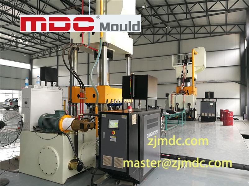
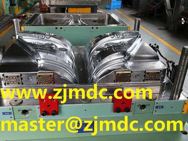
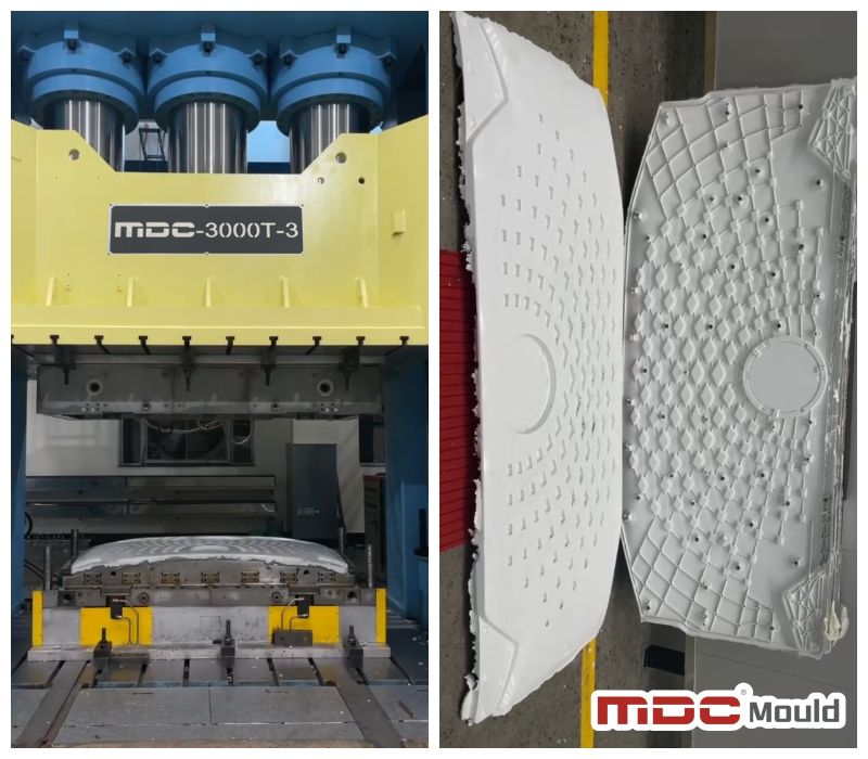
compression molding machine
compression mould machine

Typical Compression Molding Cycle Time

The cycle time for compression molding typically ranges from 1 to 10 minutes, but it can be longer for complex parts or larger components. The specific time depends on the material, mold design, and part size:

  • Simple Parts: Thin, uncomplicated parts made from thermoplastic materials may have a cycle time of 30 seconds to 2 minutes.
  • Complex Parts: For parts made from thermoset materials like SMC or BMC, the cycle time is usually between 5 to 10 minutes.
  • Thicker Parts: Larger or thicker parts requiring more material and time to cure may extend the cycle time beyond 10 minutes.

For high-volume production environments, such as in automotive or aerospace component manufacturing, optimizing cycle time is crucial for efficiency. Manufacturers constantly aim to reduce cycle time without compromising product quality.

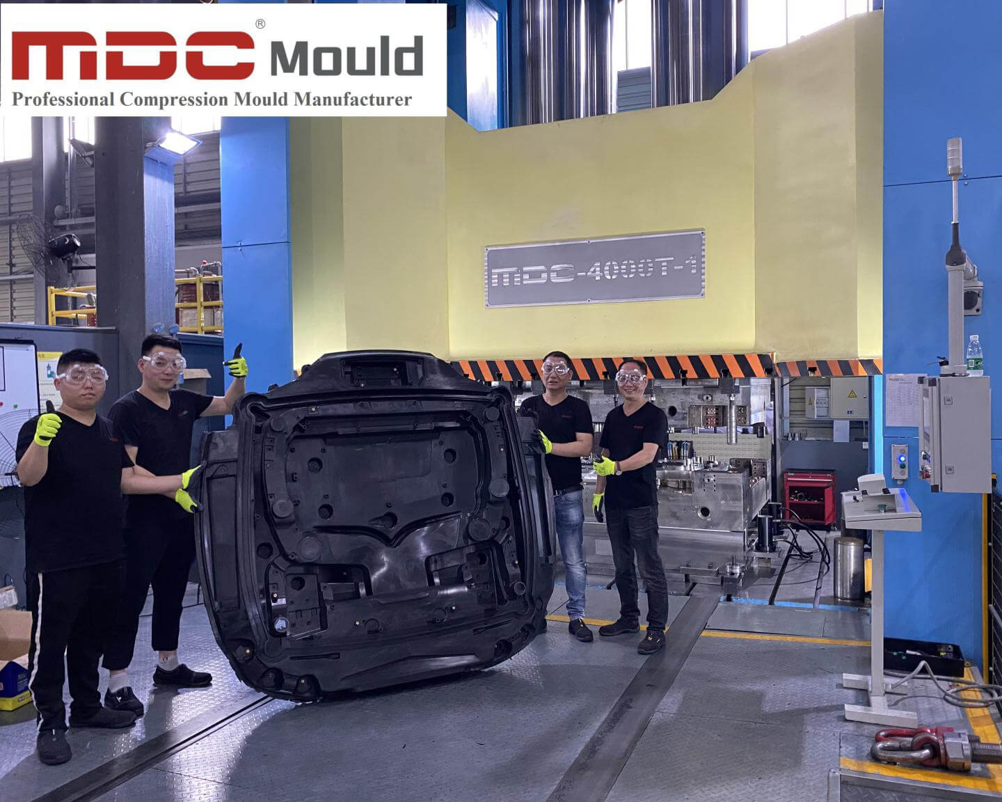
compression-molding

Compression Molding Process Breakdown

Here’s a breakdown of the typical stages of the compression molding process and their respective timeframes:

  • Preheating (Optional): Preheating the material can reduce cycle time and takes around 1 to 3 minutes.
  • Material Loading: The material is placed into the mold, which usually takes 30 seconds to 1 minute.
  • Mold Closing and Pressing: The mold is closed, and heat and pressure are applied, lasting 30 seconds to 10 minutes.
  • Curing Time: This step is crucial for thermoset materials, with times ranging from 2 to 15 minutes.
  • Cooling (Optional): Some thermoplastic parts may require a cooling phase, lasting 1 to 3 minutes.
  • Part Ejection: Once the part is cured or cooled, it is ejected from the mold, taking 10 to 30 seconds.

Strategies for Reducing Compression Molding Time

There are several ways to reduce cycle time in compression molding without sacrificing quality:

  • Optimize Material Flow: Improving material flow can ensure faster filling of the mold cavity.
  • Preheating: Preheating the material before molding reduces pressing and curing times.
  • Automation: Automated loading and ejection systems can streamline the process.
  • Multi-Cavity Molds: Using molds with multiple cavities allows multiple parts to be produced simultaneously.
  • Optimize Mold Temperature: Advanced temperature control systems can maintain optimal mold temperatures to reduce cycle time.
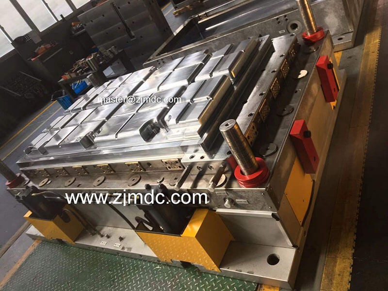
compression tooling

Conclusion

Compression molding time can vary significantly based on factors like material type, part thickness, mold design, and temperature. The cycle time typically ranges from 1 to 10 minutes, but larger or more complex parts may require more time. Manufacturers who optimize key aspects of the process, such as curing time, material flow, and automation, can significantly reduce cycle times and improve production efficiency.

Understanding how long compression molding takes is essential for managing production schedules and meeting delivery timelines, especially in industries like automotiveaerospace, and consumer goods.

In-Depth Guide to Thermosetting Plastic Compression Molding Process

Explore the comprehensive process of thermosetting plastic compression molding, including equipment, techniques, and performance characteristics.

Introduction to Plastic Molding Technology

Plastic molding processing is an engineering technology involving various processes to transform plastic into products. This transformation often includes phenomena such as polymer rheology and changes in physical and chemical properties.

What is Compression Molding?

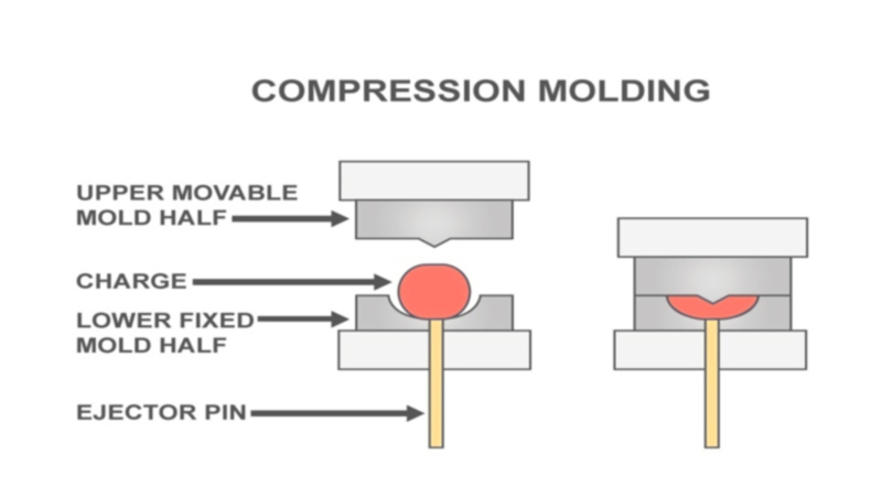
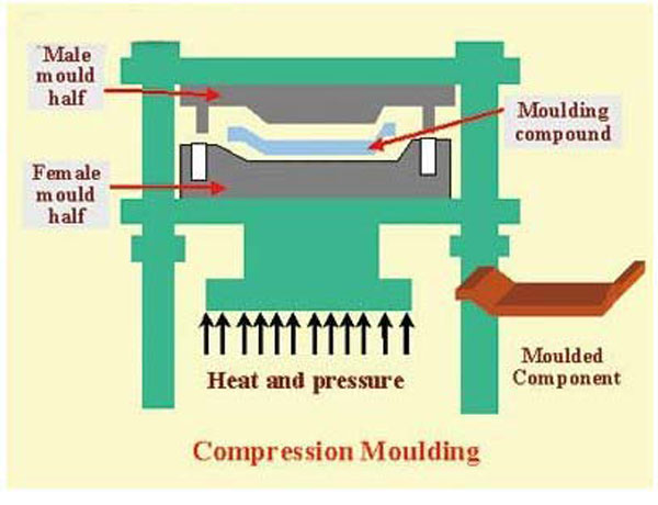
Compression molding, also known as press molding, is a primary method for forming thermosetting plastics and reinforced plastics. This process involves placing raw materials in heated molds under pressure, allowing the materials to flow and fill the cavity, and forming products through heat and pressure over time.

compression Molding Principle

Characteristics and Performance of Thermosetting Plastic Compression Molding

Process Characteristics

  • Mature technology with simple equipment and molds compared to injection molding.
  • Intermittent molding with longer production cycles and lower efficiency.
  • Produces high-quality products without internal stress or molecular orientation.
  • Can mold large-area products but not complex shapes or thick items.
  • Allows for hot demolding of products.

Performance Factors

Key performance factors include:

  1. Fluidity: The flowability impacts the molding process and product quality.
  2. Curing Rate: Influences the chemical reaction speed during molding.
  3. Shrinkage Rate: Affects dimensions and product integrity post-molding.
  4. Compression Ratio: Relates to volume change during molding.
  5. Moisture and Volatiles Content: Excessive content can affect product quality.
  6. Fineness and Uniformity: Particle size and distribution play a role in performance.
compression molding

Equipment and Molds Used in Compression Molding

The main equipment used is the press machine, which applies heat and pressure to the plastic through molds. There are two main types of hydraulic presses:

  • Top-pressing hydraulic machines.
  • Bottom-pressing hydraulic machines.
compression-mould-machine

Common mold types include:

  1. Overflow molds
  2. Non-overflow molds
  3. Semi-overflow molds

The Process Flow of Compression Molding

The typical process includes the following steps:

  1. Measuring: Accurate measurement is critical, using weight, volume, or counting methods.
  2. Pre-pressing: Reduces compression ratios and improves thermal transfer.
  3. Preheating: Increases curing speed and improves material flow.
  4. Insert Placement: Ensures correct positioning for components like conductive parts.
  5. Feeding: Accurate feeding is crucial for achieving desired product specifications.
  6. Closing Molds: Rapid initial closing followed by a slower approach to prevent damage.
  7. Ventilation: Essential for expelling gases and moisture during the process.
  8. Curing: Achieved through controlled pressure and temperature.
  9. Demolding: Typically occurs while the material is still warm, utilizing ejector rods.
  10. Post-processing: Involves additional treatments to ensure product quality.
compression molding process

Process Conditions and Control

The three critical factors in compression molding are pressure, temperature, and time. Balancing these factors optimizes product quality while minimizing production costs.

For more insights on thermosetting plastic compression molding, stay connected!

Carbon Fiber and Composite Materials: A New Era for Heavy-Load Railway Freight Cars

Discover the advancements in carbon fiber composite materials and compression molding technology that revolutionize heavy-load railway freight cars.

The Role of Carbon Fiber Composite Materials in Modern Rail Transportation

On September 10, 2024, the first batch of six carbon fiber composite heavy-load railway freight cars rolled off the production line, showcasing cutting-edge lightweight and smart designs. This significant milestone marks a breakthrough in the use of carbon fiber composite materials for heavy-load railway mobile equipment.

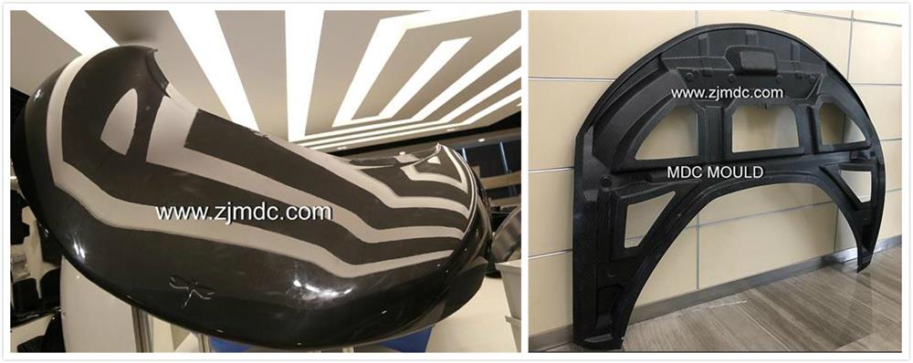
carbon fiber composite railway

Jointly developed by the China Energy Group’s Railway Equipment Company, the Beijing Low-Carbon Clean Energy Research Institute, and CRRC Qiqihar Rolling Stock Co., Ltd., these railway freight cars not only represent a leap forward in the application of new materials but also contribute to green, low-carbon rail transportation solutions.

Lightweight and Intelligent Design for Energy Efficiency

Under the guidance of national strategies like “Strengthening Transportation” and “Dual Carbon,” there is a growing demand for the green transformation of the transportation sector. The China Energy Group, managing over 57,000 railway freight cars, plays a key role in transitioning toward energy-efficient, lightweight solutions for large-scale freight operations, particularly in coal transport.

The new carbon fiber composite railway freight cars are a significant advancement in lightweight, high-strength, and low-energy solutions. These cars are a direct result of integrating compression molding technology and advanced composite materials, setting new benchmarks for efficiency and sustainability.

Advantages of Carbon Fiber Composite Materials

1. Higher Strength-to-Weight Ratio

Compared to traditional materials, carbon fiber composites offer a strength-to-weight ratio 3-5 times higher than aluminum alloys, making them ideal for heavy-load railway freight cars. This higher ratio allows for reduced vehicle weight without compromising structural integrity.

2. Reduced Weight for Increased Efficiency

The carbon fiber composite body reduces the weight of the railway freight cars by more than 20% compared to similar aluminum vehicles. This significant weight reduction, with a self-weight coefficient as low as 0.22, allows for greater load capacity and improves overall transportation efficiency.

3. Enhanced Durability and Environmental Resistance

Carbon fiber composites also exhibit superior resistance to harsh environmental conditions, making these materials more durable than traditional metals. This durability is essential for long-term operation and minimal maintenance, ensuring that these railway freight cars can withstand extreme conditions over their lifespan.

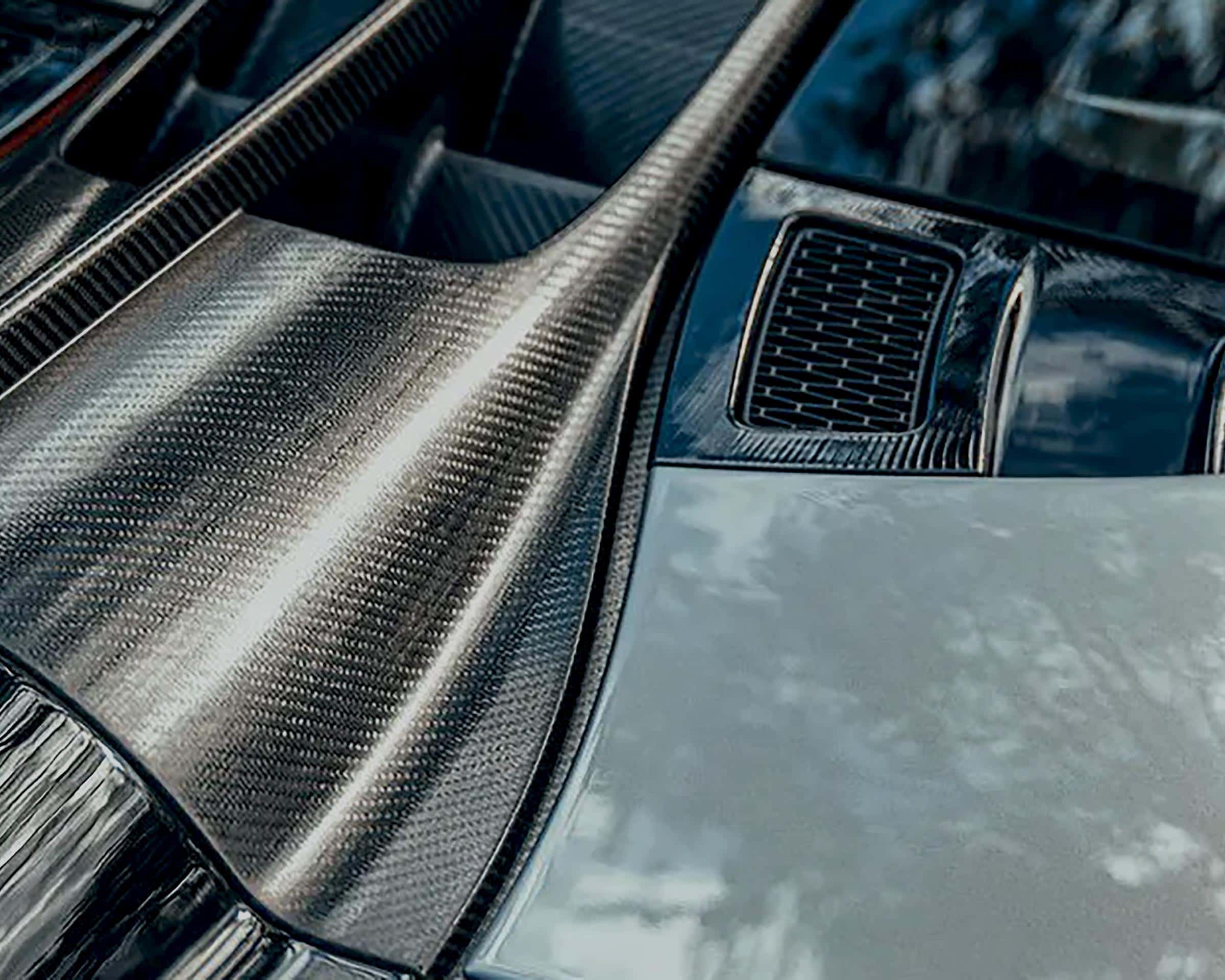
microstructure of carbon fiber

Technological Innovations in Heavy-Load Freight Cars

1. Optimized Bogies and Air Brake Systems

The new cars are equipped with optimized K6-type bogies, which enhance load distribution and stability. Integrated air brake systems ensure efficient braking, further improving the cars’ safety and control.

2. Smart Monitoring Systems for Real-Time Data Collection

These freight cars incorporate smart monitoring systems powered by IoT, big data, and cloud computing, enabling real-time data collection on the performance of the cars. This system improves predictive maintenance and helps optimize energy consumption, contributing to greener transportation solutions.

Compression Molding: A Key Manufacturing Technique

The use of compression molding for carbon fiber composite materials has been instrumental in the development of these new railway freight cars. Compression molding allows for the efficient production of large, complex parts with precision, making it ideal for large-scale components such as the car bodies.

Advantages of Compression Molding for Carbon Fiber Components

  • High precision and consistency in part production.
  • Efficient manufacturing of large parts in a single operation.
  • Minimized material waste, especially important with high-cost materials like carbon fiber.
compression mold

Conclusion: Pioneering the Future of Green Rail Transport

The successful development of carbon fiber composite heavy-load railway freight cars signals a major step forward in the future of rail transportation. With the combined benefits of lightweight design, improved durability, and cutting-edge technologies like smart monitoring systems, these cars offer revolutionary advantages for green, low-carbon transport.

As global transportation continues to evolve, the integration of composite materials and compression molding technology will remain pivotal in shaping the next generation of heavy-load railway freight equipment.

Effects of Thermoforming Parameters on Carbon Fiber Thermoplastic Composites

Discover the effects of thermoforming parameters on woven carbon fiber fabric/polycarbonate thermoplastic composites, including optimal values for spring-back angle, mold shape fitness, and key parameters for composite molds.

The quality of woven carbon fiber fabric/polycarbonate thermoplastic composites after thermoforming and demolding has been a subject of considerable research, especially for applications in industries that require SMC molds and composite molding. These composites are critical in sectors utilizing compression molds and carbon fiber molds.

This study investigates the effects of thermoforming parameters using a combination of finite element simulation and the Taguchi orthogonal array. The simulation model employed a discrete approach with a micro-mechanical model to describe the deformation behavior of the woven carbon fiber fabric, similar to what is seen in thermoforming molds and compression tooling. In parallel, a resin model was incorporated to ensure accurate simulations. This approach was validated through bias extension tests conducted at five different temperatures, providing essential data on material behavior during the thermoforming process, much like processes involving BMC molds and press molds.

composite

Key Thermoforming Parameters

The study focused on three key thermoforming parameters, each having three levels, similar to those considered in compression molding:

  • Blank Temperature: Influences the material’s flexibility and ability to conform to mold shapes, crucial in SMC tooling and BMC molding.
  • Mold Temperature: Affects the final shape fitness and surface finish of the composite, often impacting thermoforming molds and SymaLITE molds.
  • Blank Holding Pressure: Plays a crucial role in keeping the material in place and ensuring consistent molding, essential for composite molds like SMC moulds and carbon fiber molds.

The objective was to optimize four important quality factors: fiber-enclosed anglespring-back anglemold shape fitness, and the strain of the U-shaped workpiece, similar to those in thermoset molds and LFT molding. By adjusting the thermoforming parameters, the study aimed to achieve the best combination of these factors across various composite tooling methods.

mold

Results and Analysis

The finite element simulation revealed that the stress-displacement curve obtained from bias extension tests closely matched the simulated results. This verified the reliability of the discrete finite element method used in this study, which has parallels with the validation processes for SMC molding and press tooling.

Moreover, the Taguchi orthogonal array analysis identified blank holding pressure as the dominant process parameter, much like in compression molds and BMC tooling. The optimal value for blank holding pressure was found to be 1.18 kPa, making it the most critical factor in the thermoforming process. Blank temperature was the second most influential factor, with an optimal range of 160°C to 230°C. Interestingly, mold temperature had a relatively minor effect on the final composite quality, similar to the behavior observed in GMT molds and D-LFT molds.

Optimal Thermoforming Settings

The study recommended the following optimal settings for the thermoforming of woven carbon fiber fabric/polycarbonate thermoplastic composites:

  • Blank Holding Pressure: 1.18 kPa (critical for compression molds and SMC moulds)
  • Blank Temperature: 230°C (relevant for thermoforming tools and hot compression molds)
  • Mold Temperature: 190°C (beneficial for composite molding and carbon fiber molds)

These settings resulted in the most favorable outcomes for all four quality factors, indicating that careful control of blank holding pressure and temperature is crucial for achieving high-quality composite molds and thermoforming molds.

The-model-of-the-thermoforming-process

Conclusion

In summary, the results of this study provide valuable insights into the effects of thermoforming parameters on woven carbon fiber fabric/polycarbonate thermoplastic composites. The study concluded that blank holding pressure and blank temperature are the two most important factors, with mold temperature playing a secondary role. These findings are essential for those working with composite toolingthermoforming tools, and compression molds, providing a clear pathway for producing high-quality composites with desirable spring-back angle, fiber-enclosed angle, and mold shape fitness.

Composite Materials and Processes: Unique Materials Requiring Unique Processes

Discover the unique characteristics and processes of composite materials, including SMC mold, BMC tooling, and carbon fiber molding. Learn about their impact on industries like aerospace, automotive, marine, and sports equipment.

Composite materials, including those produced with SMC mold and BMC tooling, have emerged as game-changing solutions across various industries due to their unique properties, such as a high strength-to-weight ratio and anisotropic behavior. These characteristics have led to the increasing popularity and adoption of composites in industries like aerospace, automotive, marine, and sports equipment.

SCHEMATIC PICTURE OF A COMPOSITE LAMINATE

Introduction to Composite Materials and Processes

Composite materials, often crafted using processes such as SMC molding and GMT tooling, offer unique advantages due to their tailored strength and stiffness. These characteristics are achieved through strategic placement and orientation of fibers within the matrix, optimizing the material for specific performance requirements.

Laminate Composites

Laminate composites are continuous fiber composites where individual layers are oriented in a manner that enhances strength in the primary load-bearing direction. This method is often employed in SMC moulding and BMC molding to create high-performance components. Essentially, laminates consist of multiple layers of fibers arranged to optimize their strength and stiffness.

Fiber’s Key Role in Composites: Balancing Strength, Stiffness, and Durability

Fibers in composites play a critical role in providing strength and stiffness. Typically made from high-strength materials like carbon, glass, or aramid, fibers bear the majority of the load due to their superior strength and stiffness, while the polymer matrix binds them and facilitates load transfer between fibers. This is particularly evident in carbon fiber mold applications.

SHEMATIC PICTURE OF THE LAYUP USED-FOR ALL COMPOSITE PARTS IN THE WING BOX SUBASSEMBLY
Matrix Material’s Fundamental Functions in Composites: Protection, Load Transfer, and Thermal Resistance

The matrix in composites serves several essential functions. It protects the fibers, maintains their proper alignment, and facilitates load transfer between them. Additionally, the matrix helps distribute compressive loads across all fibers in the composite, which is crucial in applications involving press molds and compression tooling.

Unique Materials and Processes

The unique properties of composites, such as a high strength-to-weight ratio and anisotropic behavior, significantly influence the design and engineering of composite components. Processes like thermoforming mold and SymaLITE mould are tailored to meet specific performance requirements by strategically placing and orienting fibers within the matrix.

Advantages of Composites

The use of composites, particularly those produced with LFT molding and D-LFT moulding, across various industries offers benefits like improved performance, weight reduction, and enhanced fuel efficiency. In aerospace, composites make aircraft structures lighter, leading to lower fuel consumption and emissions. In automotive, composites like those using hot compression mold and BMC moulding improve crashworthiness and vehicle performance.

Challenges Associated with Composite Manufacturing

Manufacturing composites presents its own set of challenges, including delamination, quality control, and the need for specialized tools and equipment such as thermoforming tooling and compression molds. To mitigate these challenges, careful design and planning, stringent quality control measures, and proper operator training and education are crucial.

composite compression Manufacturing Process
Conclusion

Understanding the unique properties of composites and their manufacturing processes, including those involving SMC tools and thermoset molds, is crucial for the successful design and engineering of composite components. By leveraging these unique materials and processes, industries can benefit from improved performance, weight reduction, and enhanced fuel efficiency. As the adoption of composites continues to rise, overcoming the challenges associated with manufacturing is essential to unlocking their full potential in various applications.

Solving Demolding Challenges with MDC Mould’s Innovative Design

Discover how MDC Mould solves demolding challenges with innovative mold design, high-quality materials, and precise temperature control.

Introduction

Demolding issues are common in mold manufacturing, leading to production delays and increased costs. MDC Mould, a leader in mold manufacturing, addresses these challenges with innovative solutions, advanced technologies, and superior mold design. This article explores how MDC Mould enhances the demolding process, ensuring efficient and reliable production.

Understanding Demolding Challenges

Demolding difficulties arise when molded parts adhere too strongly to the mold surface, making removal challenging. Factors contributing to this include material adhesion, poor mold design, surface condition, and temperature control. MDC Mould addresses these issues through innovative design, precision engineering, and advanced materials.

MDC Mould’s Solutions to Demolding Issues

1. High-Performance Mold Release Agents

MDC Mould integrates high-quality mold release agents to reduce friction between the mold and material. These agents are selected based on the specific material and application, ensuring optimal demolding performance and extending mold life.

mold

2. Optimized Mold Design

MDC Mould focuses on proper draft angles, smooth transitions, and manageable undercuts in their designs. By eliminating sharp edges and reducing complex geometries, MDC ensures easy and damage-free demolding.

3. Advanced Surface Treatments

MDC Mould applies advanced surface treatments, such as polishing and coating, to ensure a smooth, frictionless mold surface. These treatments improve demolding performance and enhance the quality of finished parts.

demolding

4. Precise Temperature Control

MDC Mould uses state-of-the-art heating and cooling systems to maintain optimal mold temperatures. Proper temperature control prevents issues such as warping and sticking, ensuring consistent and predictable demolding.

5. Custom Material Selection

MDC Mould collaborates with clients to select materials that are compatible with their molds. By choosing materials with lower adhesion properties, MDC ensures easy demolding without compromising quality.

6. Mechanical Ejection Systems

For complex molds, MDC Mould incorporates mechanical ejection systems like ejector pins or lifters. These systems provide additional force for smooth and efficient demolding, even with challenging molds.

Why Choose MDC Mould?

MDC Mould’s expertise in solving demolding challenges is reflected in their advanced mold designs, customization options, and cutting-edge technology. Whether dealing with SMC moldsBMC molds, or large-scale compression molds, MDC Mould offers solutions that minimize demolding difficulties and ensure consistent, high-quality production.

compression mold

Conclusion

Demolding challenges can significantly impact production efficiency and quality. MDC Mould’s comprehensive approach to mold design, material selection, surface treatment, and temperature control ensures superior performance, even in demanding applications. By choosing MDC Mould, you’re investing in reliable, high-quality molds engineered to solve your demolding challenges.

What is the Difference Between a Positive Mold and a Negative Mold in Thermoforming?

Discover the differences between positive and negative molds in thermoforming, and explore how they impact composite mold, compression mold, SMC mold, BMC mold, carbon fiber mold, and thermoforming mold applications.

Thermoforming is a widely used process in the manufacturing industry, especially when producing plastic components. The process involves heating a plastic sheet until it becomes pliable and then shaping it against a mold. In thermoforming, the mold type plays a crucial role in determining the final product’s quality, accuracy, and surface finish. Two primary types of molds are used in this process: the positive mold (also known as the male mold) and the negative mold (also known as the female mold). Understanding the differences between these molds is essential for anyone involved in thermoforming or related fields such as composite mold and compression mold manufacturing.

compression-molding

Positive Mold (Male Mold)

A positive mold, or male mold, is a type of mold where the material is formed over the exterior surface. The mold itself represents the shape that will be transferred to the inner surface of the final product. This means that the material is stretched over the mold, with the exterior of the material taking the shape of the mold’s exterior.

Key Characteristics of Positive Molds:

  • Surface Finish: The outer surface of the product directly contacts the mold, providing a high-quality finish on the internal surface. This is ideal for applications where the inner surface’s texture or appearance is critical.
  • Material Stretching: The plastic sheet is stretched over the mold, which can lead to thinning in areas, especially around corners and edges.
  • Application: Positive molds are often used when the internal dimensions are more important than external ones. For example, in applications involving thermoforming molds for containers or trays, where the inside must be smooth and accurate.
thermoforming

Negative Mold (Female Mold)

A negative mold, or female mold, is the inverse of a positive mold. In this case, the material is drawn into the mold, allowing the outer surface of the material to match the mold’s interior. The external surface of the final product mirrors the internal surface of the negative mold.

Key Characteristics of Negative Molds:

  • Surface Finish: The outer surface of the product takes the finish of the mold’s interior. This results in a high-quality surface on the exterior of the final product.
  • Material Thickness: Since the material is drawn into the mold, it tends to maintain a more consistent thickness, which is beneficial for applications requiring uniform strength.
  • Application: Negative molds are used when the external appearance and dimensions of the product are critical. This is common in composite molds and compression molds, where external aesthetics are important.

Comparing Positive and Negative Molds

Both positive and negative molds have their advantages and limitations, and the choice between them depends on the specific requirements of the application.

  • Surface Quality: Positive molds offer a superior finish on the internal surface, whereas negative molds provide a better finish on the external surface.
  • Material Distribution: Negative molds tend to produce parts with more uniform wall thickness, making them ideal for applications requiring consistent material strength.
  • Design Flexibility: Positive molds may lead to thinning in the material at sharp corners, which could be a limitation in certain designs.
thermoforming moulding

Applications in Composite Molding

The principles of positive and negative molds extend beyond traditional thermoforming into the realm of composite molding. In composite molds used for producing high-performance parts, such as carbon fiber molds, the choice between positive and negative molds can impact the final part’s structural integrity and surface quality.

  • SMC Mold and BMC Mold: Both Sheet Molding Compound (SMC) and Bulk Molding Compound (BMC) processes utilize molds that must withstand high pressures and temperatures. Here, the choice of a positive or negative mold can affect the part’s surface texture and material flow.
  • Carbon Fiber Mold: In carbon fiber mold manufacturing, the mold type influences the fiber alignment and resin distribution, crucial for achieving the desired strength-to-weight ratio.

Conclusion

Understanding the difference between positive and negative molds in thermoforming is essential for optimizing the manufacturing process. Positive molds provide high-quality internal surfaces but can lead to material thinning, while negative molds offer uniform material distribution and superior external finishes. Whether in traditional thermoforming or advanced composite molding applications, choosing the right mold type is crucial for achieving the desired product characteristics. As technologies evolve, the principles behind positive and negative molds continue to shape industries ranging from packaging to aerospace, highlighting their ongoing importance in manufacturing.

Mastering Composite Mold Casting: A Comprehensive Guide with a Composite Mold Making Kit

Learn about composite mold casting and how a composite mold making kit can streamline your production process. Explore related terms like compression mold, SMC mold, BMC molding, and more.

Composite materials have become essential in various industries, thanks to their exceptional strength-to-weight ratiocorrosion resistance, and design flexibility. From aerospace to automotive, the demand for lightweight, durable, and high-performance components has driven the evolution of composite mold casting techniques. To meet these industry needs, the use of a composite mold making kit has become increasingly popular, offering an all-in-one solution for creating high-quality molds.

What is Composite Mold Casting?

Composite mold casting is a process used to create complex shapes and forms from composite materials. These materials typically include reinforced plastics such as carbon fiber, fiberglass, or BMC (Bulk Molding Compound) used in BMC molding and BMC moulding. The mold defines the shape of the final product and is critical for the success of the compression molding process.

The quality of the mold directly impacts the quality of the final product, which is why precision in mold making is crucial. This process is widely used in industries such as thermoforming mouldthermoforming tooling, and thermoset mold production.

BMC

The Composite Mold Casting Process

  1. Mold Design and Fabrication: The first step is designing the mold, often using CAD software to create a precise model. Molds can be made from materials such as aluminum, steel, or even composites.
  2. Surface Preparation: The mold surface must be prepared to ensure a smooth finish on the final product, often involving the application of a release agent to prevent the composite material from sticking.
  3. Lay-Up Process: Layers of composite material, such as those used in SMC molds and composite molds, are placed into the mold to optimize the strength and stiffness of the final product.
  4. Curing: The mold is placed in an oven or autoclave to cure, solidifying the resin matrix and forming a rigid structure. This step is critical in composite molding and thermoforming mold processes.
  5. Demolding and Finishing: After curing, the part is carefully removed from the mold. Additional processes such as trimming, sanding, and painting may be applied to achieve the desired finish.
BMC mould

The Role of a Composite Mold Making Kit

composite mold making kit is an invaluable resource, especially for professionals working with compression moldsthermoforming tools, or composite molds. These kits include all necessary materials and tools to create high-quality molds, streamlining the process and minimizing errors.

What’s Included in a Composite Mold Making Kit?

  • Resins and Hardeners: Essential for creating the mold itself, these components ensure proper curing and durability, vital in thermoset molding.
  • Reinforcing Fibers: Some kits include fibers like fiberglass to strengthen the mold, particularly in high-stress areas.
  • Release Agents: These agents prevent the composite material from sticking to the mold during casting, ensuring easy demolding.
  • Mixing Tools: Brushes, mixing cups, and stir sticks are included to help apply the resin and hardener accurately.
  • Instructional Guides: Many kits provide detailed instructions or access to tutorials, making it easier for beginners to understand the mold-making process.
composite molding

Benefits of Using a Composite Mold Making Kit

Using a composite mold making kit offers several advantages, particularly for those working in thermoforming tool and composite molding:

  • Convenience: Kits offer a convenient solution by providing all necessary materials in one package.
  • Cost-Effective: Purchasing a kit can be more affordable than buying each material individually, and it reduces the risk of buying incompatible products.
  • Quality Assurance: Kits are typically designed by professionals, ensuring high-quality materials and compatibility.
  • Time-Saving: The mold-making process is expedited with all materials readily available, reducing preparation time.

Applications of Composite Mold Casting

Composite mold casting has a wide range of applications across various industries:

  • Aerospace: Used to create lightweight, strong components like aircraft wings and fuselage sections.
  • Automotive: Essential for producing parts like bumpers and dashboards, where weight reduction is crucial.
  • Marine: Composite materials are used to create boat hulls and decks, offering excellent corrosion resistance.
  • Sports Equipment: Composite materials are favored for their strength and lightweight properties in products like tennis rackets and bicycle frames.
compression mold

Conclusion

Composite mold casting is a sophisticated process vital to manufacturing high-performance components across various industries. Utilizing a composite mold making kit streamlines the process, offering a comprehensive solution that saves time, reduces costs, and ensures the production of top-tier molds. Whether you’re working with SMC moldsthermoforming molds, or thermoset molds, mastering the art of composite mold casting with the right tools is essential for success.

What are the Three Differences Between Compression Molding and Injection Molding?

Explore the three key differences between compression molding and injection molding, and understand their unique applications and benefits in manufacturing.

In the world of manufacturing, two popular methods for producing plastic and composite parts are compression molding and injection molding. While both techniques are used to create high-quality components, they differ significantly in terms of process, materials, and applications. In this article, we will delve into the three primary differences between compression molding and injection molding, providing a detailed comparison to help you understand which method might be best suited for your needs.

compression-moulding

1. Process and Mechanism

Compression Molding

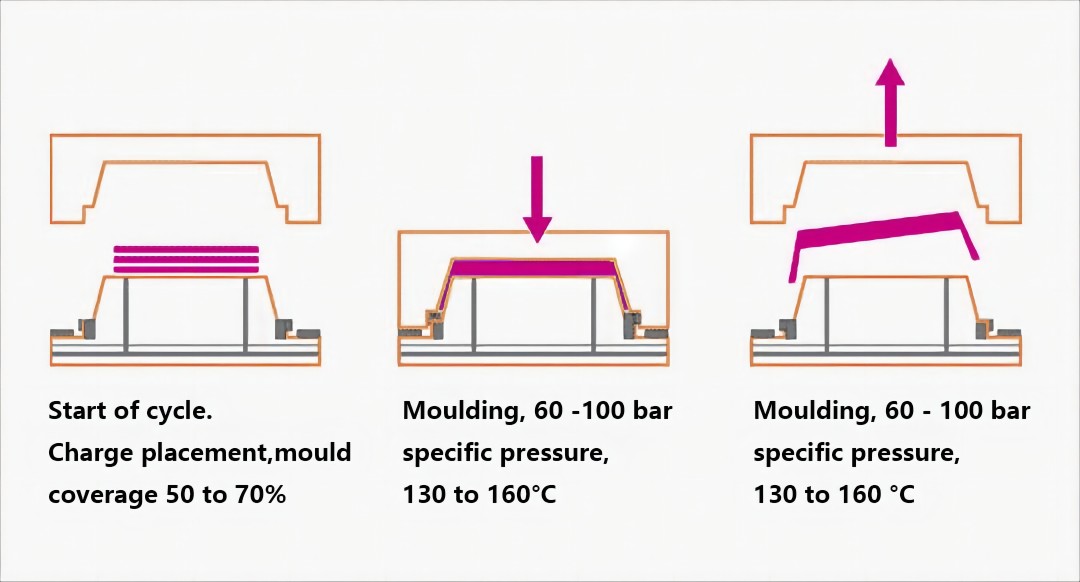
Compression molding involves placing a pre-measured amount of material, known as a charge, into an open mold cavity. The mold is then closed, and heat and pressure are applied to shape the material into the desired form. The heat causes the material to become pliable, and the pressure forces it to conform to the shape of the mold. Once the material has cured and solidified, the mold is opened, and the finished part is removed.

This process is typically used for thermosetting plastics and composites, which require high pressure and temperature to mold. Compression molding is ideal for producing large, intricate parts with high strength and durability.

Injection Molding

Injection molding, on the other hand, involves melting plastic pellets and injecting the molten material into a closed mold under high pressure. The mold is held under pressure until the material cools and solidifies. Once the part has cooled sufficiently, the mold is opened, and the finished part is ejected.

Injection molding is commonly used for thermoplastics, which can be melted and solidified multiple times. This process is highly efficient for producing large volumes of small to medium-sized parts with complex geometries.

injection molding

2. Materials Used

Compression Molding

Compression molding is predominantly used for thermosetting plastics and composite materials. Thermosets are polymers that irreversibly cure, meaning they cannot be melted and reshaped once cured. Common materials used in compression molding include phenolic resins, epoxy resins, and unsaturated polyester resins. These materials offer excellent mechanical properties, heat resistance, and dimensional stability, making them suitable for high-performance applications.

Additionally, compression molding is often used for producing parts from fiber-reinforced composites, such as carbon fiber or glass fiber, which provide superior strength-to-weight ratios and enhanced structural integrity.

Injection Molding

Injection molding primarily utilizes thermoplastic materials, which can be melted and re-melted multiple times without undergoing any significant chemical change. Common thermoplastics used in injection molding include polyethylene (PE), polypropylene (PP), polystyrene (PS), and acrylonitrile butadiene styrene (ABS). These materials offer versatility, ease of processing, and the ability to produce parts with precise dimensions and smooth finishes.

Injection molding can also be used for thermoplastic elastomers (TPE) and some thermosets, although this is less common. The ability to use a wide range of thermoplastic materials makes injection molding suitable for a diverse array of applications, from automotive components to consumer electronics.

3. Applications and Suitability

Compression Molding

Compression molding is well-suited for producing large, complex parts with high strength and durability. This process is commonly used in the automotive, aerospace, and electrical industries for manufacturing components such as:

  • Automotive body panels
  • Electrical insulators
  • Composite parts for aircraft
  • Heavy-duty industrial equipment

The ability to mold fiber-reinforced composites makes compression molding an ideal choice for applications requiring high performance and structural integrity.

compression moulded tractor roof

Injection Molding

Injection molding is highly efficient for mass-producing small to medium-sized parts with intricate designs and tight tolerances. This process is widely used across various industries, including:

  • Consumer electronics (e.g., housings for electronic devices)
  • Medical devices (e.g., syringes, medical instrument components)
  • Automotive components (e.g., dashboard parts, clips, and fasteners)
  • Packaging (e.g., caps and closures for bottles)

The high production speed and ability to produce parts with consistent quality make injection molding a preferred method for high-volume manufacturing.

Conclusion

Both compression molding and injection molding have their unique advantages and are suited for different types of applications. Compression molding is ideal for producing large, durable parts from thermosetting plastics and composites, while injection molding excels in creating small to medium-sized parts from thermoplastics with high efficiency and precision.

Understanding the differences between these two molding techniques can help manufacturers choose the most appropriate method for their specific needs, ensuring optimal performance, cost-effectiveness, and quality in their final products.

Why SMC Meter Boxes are Preferred Over Metal or Plastic?

Discover why SMC meter boxes are preferred over metal or plastic. Learn about their insulating properties, cost-effectiveness, durability, fire resistance, and thermal stability.

Superior Insulating Properties

One of the most significant advantages of SMC meter boxes over metal counterparts is their excellent insulating properties. Unlike metal, SMC does not conduct electricity. This non-conductive nature provides a crucial safety benefit:

  • Safety: SMC meter boxes do not pose an electrical hazard when touched by a live wire. This reduces the risk of electric shock, making them safer for both installers and end-users.
  • No Grounding Required: Because they are non-conductive, SMC meter boxes do not need to be grounded. This simplifies the installation process, saving both time and money.
meter box mould

Cost-Effectiveness and Ease of Installation

SMC meter boxes offer significant cost advantages over both metal and traditional plastic options. Here’s how:

  • Material Costs: SMC is generally less expensive to produce than metal, and it offers a better performance-to-cost ratio than many plastics.
  • Lightweight: SMC is much lighter than metal, which makes the meter boxes easier to handle and install. This reduces labor costs and minimizes the risk of injury during installation.
  • Ease of Manufacturing: SMC can be molded into complex shapes with high precision, allowing for the integration of various features into a single part, which reduces assembly time and costs.

High Mechanical Strength and Durability

One of the key reasons for the popularity of SMC in meter box manufacturing is its high mechanical strength and durability:

  • Resistance to Stress and Impact: SMC has high tensile strength, meaning it can withstand significant stress without cracking or breaking. This makes it suitable for outdoor applications where it may be exposed to harsh conditions.
  • Long Lifespan: The robust nature of SMC ensures that meter boxes have a long service life, reducing the need for frequent replacements and maintenance.

Fire Resistance and Safety

Fire safety is a critical consideration for any electrical enclosure, and SMC excels in this area:

  • Self-Extinguishing Properties: SMC can be formulated to be self-extinguishing, which means it will not catch fire easily and can prevent the spread of flames in the event of a fire. This property is especially important for electrical applications where the risk of fire is a concern.
  • Thermal Stability: As a thermoset plastic, SMC does not melt at high temperatures. This characteristic enhances the safety and integrity of the meter box in extreme conditions.
SMC Mold

Thermal Stability

In addition to its fire resistance, SMC’s thermal stability provides further benefits:

  • High Temperature Tolerance: SMC mold can withstand high temperatures without deforming or losing its mechanical properties. This makes it ideal for use in environments where it may be exposed to heat.
  • Consistency in Performance: The material’s stability ensures that it maintains its performance characteristics over a wide range of temperatures, providing reliable protection for the electrical components housed within the meter box.

Manufacturing Process of SMC Enclosures

To better understand the advantages of SMC meter boxes, it is helpful to look at the manufacturing process. MDC, a leader in SMC enclosure mold manufacturing, demonstrates the efficiency and precision of this process.

  1. Material Preparation
    • Compounding: SMC is created by combining resin, fillers, and reinforcement materials, such as glass fibers, into a dough-like compound. This mixture is then rolled into sheets.
    • Storage: The SMC sheets are stored and allowed to mature, which helps to achieve the desired consistency and properties for molding.
  2. Molding Process
    • Mold Setup: The matured SMC sheets are placed into a heated mold cavity.
    • Compression Molding: The mold is closed, and heat and pressure are applied. The SMC material flows to fill the mold cavity, taking on the desired shape. This process ensures high precision and the ability to produce complex geometries.
    • Curing: The heat initiates a chemical reaction that cures the SMC, transforming it into a rigid, solid form. The curing process ensures that the molded part has the desired mechanical and physical properties.
  3. Finishing
    • Trimming and Drilling: After molding, the parts may require trimming of excess material and drilling of holes for mounting or other features.
    • Surface Treatment: Depending on the application, the SMC meter boxes may undergo additional surface treatments to enhance their appearance or performance, such as painting or coating.
  4. Quality Control
    • Inspection: Each meter box is inspected for defects and to ensure it meets the required specifications.
    • Testing: Functional tests, such as impact resistance and electrical insulation tests, are conducted to verify the performance of the meter boxes.
SMC enclosure mold

Conclusion

The shift from metal and traditional plastic to SMC for meter box manufacturing is driven by the numerous advantages SMC ( composite mold ) offers. Its superior insulating properties, cost-effectiveness, ease of installation, high mechanical strength, fire resistance, and thermal stability make SMC meter boxes an ideal choice for modern electrical enclosures. The precision and efficiency of the SMC manufacturing process further enhance these benefits, ensuring high-quality, durable products. As a leader in SMC enclosure mold manufacturing, MDC exemplifies the capabilities and advantages of this innovative material, setting a standard for safety, reliability, and performance in the industry.